Lunes, Agosto 25, 2014

Superposition Theorem


Superposition Theorem

The superposition theorem for electrical circuits states that for a linear system the response (voltage or current) in any branch of a bilateral linear circuit having more than one independent source equals the algebraic sum of the responses caused by each independent source acting alone, where all the other independent sources are replaced by their internal impedances.
To ascertain the contribution of each individual source, all of the other sources first must be "turned off" (set to zero) by:
  1. Replacing all other independent voltage sources with a short circuit (thereby eliminating difference of potential i.e. V=0; internal impedance of ideal voltage source is zero (short circuit)).
  2. Replacing all other independent current sources with an open circuit (thereby eliminating current i.e. I=0; internal impedance of ideal current source is infinite (open circuit)).
This procedure is followed for each source in turn, then the resultant responses are added to determine the true operation of the circuit. The resultant circuit operation is the superposition of the various voltage and current sources.

Simple Steps to Apply Superposition Principle:

1.     Turn off all independent sources except one source. Find the output (voltage or current) due to that active source using nodal or mesh analysis.

2.     Repeat step 1 for each of the other independent sources.

3.     Find the total contribution by adding algebraically all the contributions due to the independent sources.

Another point that should be considered is that superposition only works for voltage and current but not power. In other words the sum of the powers of each source with the other sources turned off is not the real consumed power. To calculate power we should first use superposition to find both current and voltage of each linear element and then calculate the sum of the multiplied voltages and currents.


Overview and Insights
           In this week we discussed about the superposition theorem, where one of the sources is removed and the other is solved using voltage division or current division. In using the Superposition, we replace the voltage source with a short circuit on its place, and an open circuit when we replace the current source. We turn off other independent sources except one source. After converting the circuit by superposition, we can use nodal and mesh analysis or any other techniques to get the value of the output voltage or current. We add the two results to get the answer.
Example: Vo = Va + Vb  or  Io = Ia + Ib


Linggo, Agosto 17, 2014

Linearity Property and Source Transformation

Linearity property

This property gives linear and nonlinear circuit definition. The property can be applied in various circuit elements. The homogeneity (scaling) property and the additive property are both the combination of linearity property.The homogeneity property is that if the input is multiplied by a constant k then the output is also multiplied by the constant k. Input is called excitation and output is called response here. As an example if we consider ohm’s law. Here the law relates the input i to the output v.

Mathematically,              
v= iR

If we multiply the input current  i by a constant k then the output voltage also increases correspondingly by the constant k. The equation stands,     
kiR = kv

The additive property is that the response to a sum of inputs is the sum of the responses to each input applied separately.

Using voltage-current relationship of a resistor if

v1 = i1R       and   v2 = i2R

Applying (i1 + i2) gives

V = (i1 + i2) R = i1R+ i2R = v1 + v2

We can say that a resistor is a linear element. Because the voltage-current relationship satisfies both the additive and the homogeneity properties.

We can tell a circuit is linear if the circuit both the additive and the homogeneous. A linear circuit always consists of linear elements, linear independent and dependent sources.


What is a linear circuit?


what is linear circuit

The linear circuit is excited by another outer voltage source vs. Here the voltage source vs acts as input. The circuit ends with a load resistance R. we can take the current I through R as the output.


source transformation


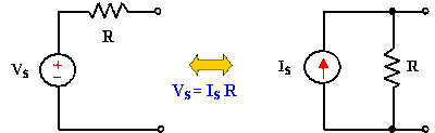
Source transformation is simplifying a circuit solution, especially with mixed sources, by transforming a voltage into a current source, and vice-versa.  Finding a solution to a circuit can be difficult without using methods such as this to make the circuit appear simpler. Source transformation is another tool for simplifying circuits. Basic to these tools is the concept of equivalence.


 A Source Transformation is the process of replacing a voltage source Vs in series with a resistor R by a current source Is in parallel with a resistor R, or vice-versa.

Source transformation requires that,

Vs = IsR     or     Is = Vs/R

Source transformation also applies to dependent sources, provided we carefully handle the dependent variable. As shown in below, a dependent voltage source in series with a resistor can be transformed to a dependent current source in parallel with the resistor or vice versa.


OVERVIEW AND INSIGHTS

Linearity Property talks about the voltage (v) and current (i), whereas voltage is directly proportional to the current, that is, when the voltage is increasing the current also increasing and vice-versa. I also learned that Source Transformation is only applicable to simple circuits and not in a complicated circuits.

Source Transformation can be applied if and only if the voltage is in series with the resistor and/or the current is in parallel with the resistor.

In Source Transformation you need to check the polarity of the source, when the polarity of the voltage source has a positive on top therefore the resulting current source is pointing upward and vice-versa. Also when the voltage source is dependent therefore the resulting current is also dependent, same calculations with independent sources.


Linggo, Agosto 10, 2014

Mesh Analysis

Mesh Analysis

Mesh analysis (or the mesh current method) is a method that is used to solve planar circuits for the currents (and indirectly the voltages) at any place in the circuit. Planar circuits are circuits that can be drawn on a plane surface with no wires crossing each other. A more general technique, called loop analysis (with the corresponding network variables called loop currents) can be applied to any circuit, planar or not. Mesh analysis and loop analysis both make use of Kirchhoff’s voltage law to arrive at a set of equations guaranteed to be solvable if the circuit has a solution. Mesh analysis is usually easier to use when the circuit is planar, compared to loop analysis.


Steps to determine mesh currents:

1.)    Assign mesh currents i1,i2, . . . . in to the n meshes.

2.)    Apply KVL to each of the n meshes. Use Ohm’s law to express the voltages in terms of the mesh currents.

3.)    Solve the resulting n simultaneous equations to get the mesh currents


Essential meshes of the planar circuit labeled 1, 2, and 3. R1, R2, R3, 1/sc, and Ls represent the impedance of the resistorscapacitor, and inductor values in the s-domain. Vs and is are the values of the voltage source and current source, respectively.


 Circuit with mesh currents labeled as i1, i2, and i3. The arrows show the direction of the mesh current.


What is Super mesh?

A super mesh occurs when a current source is contained between two essential meshes. The circuit is first treated as if the current source is not there. This leads to one equation that incorporates two mesh currents. Once this equation is formed, an equation is needed that relates the two mesh currents with the current source. This will be an equation where the current source is equal to one of the mesh currents minus the other. The following is a simple example of dealing with a super mesh.

  \begin{cases}
\text{Mesh 1, 2: } -V_s + R_1I_1 + R_2I_2 = 0\\
\text{Current source: } I_s = I_2 - I_1
\end{cases} \,


Circuit with a super mesh. Super mesh occurs because the current source is in between the essential meshes.


OVERVIEW AND INSIGHTS

A mesh current is a current that loops around and the equations are set solved in terms of them. A mesh current may not correspond to any physically flowing current, but the physical currents are easily found from them. It is usual practice to have all the mesh currents loop in the same direction. This helps prevent errors when writing out the equations. The convention is to have all the mesh currents looping in a clockwise direction.
in  Mesh analysis it is a method that is used to solve planar circuits for the currents at any place in the circuit. Planar circuits are circuits that can be drawn on a plane.
From my own understanding a mesh I a loop that does not contain any other loop within it.


Linggo, Agosto 3, 2014

Wye-Delta Transformation

The Y-Δ transform, also written wye-delta and also known by many other names, is a mathematical technique to simplify the analysis of an electrical network. The name derives from the shapes of the circuit diagrams, which look respectively like the letter Y and the Greek capital letter Δ. This circuit transformation theory was published by Arthur Edwin Kennelly in 1899. It is widely used in analysis of three-phase electric power circuits.
A delta-wye transformer is a type of three-phase electric power transformer design that employs delta-connected windings on its primary and wye/star connected windings on its secondary. A neutral wire can be provided on wye output side. It can be a single three-phase transformer, or built from three independent single-phase units. An equivalent term is delta-star transformer. Delta-wye transformers are common in commercial, industrial, and high-density residential locations, to supply three-phase distribution systems.


Δ and Y circuits with the labels


Transformation Formulas


 \


Learnings and overview:

A bridge circuit can be simplified to a series/parallel circuit by converting half of it from a Δ to a Y network. After voltage drops between the original three connection points (A, B, and C) have been solved for, those voltages can be transferred back to the original bridge circuit, across those same equivalent points.

In solving the wye-delta and delta-wye transformation it is easier to determine the labels by creating a free body diagram of it with labels and transformed circuit. In this way you can easily solve for the total resistance of the circuit, and by the help of my past learnings in the series-parallel connections I can now understand how to solve the problems given. I have sometimes difficulties in determining the labels but I will try to research and study more about it :)


Lunes, Hulyo 28, 2014

Nodal Analysis


In electric circuits’ analysis, nodal analysis, node-voltage analysis, or the branch current method is a method of determining the voltage (potential difference) between "nodes" (points where elements or branches connect) in an electrical circuit in terms of the branch currents. Nodal Analysis provides a general procedure for analyzing circuits using node voltages as the circuit variables. 


Steps to Determine Node Voltages:

1. Select a node as the reference node, Assign voltages v1, v2, . . . . . , 
vn-1 to the remaining n-1 nodes. The voltages are referenced with respect to the reference node.

2.Apply KCL to each of the n-1 non-reference nodes. Use Ohm’s law to express currents in terms of node voltages.

3. Solve the resulting simultaneous equations to obtain the unknown node voltages.


Nodal Analysis with Voltage Sources


Case 1: If the voltage source (dependent or independent) is connected between two non-reference nodes, the two non-reference nodes form a generalized node or super node, we apply both KCL and KVL to determine the node voltages.

Case 2: if a voltage source is connected between the reference node and a non-reference node, we simply set the voltage at the non-reference node equal to the voltage of the voltage source in figure 2 for example,

v1 = 20V


What is supernode?

A supernode is formed by enclosing a (dependent or independent) voltage source connected between two non-reference nodes and any elements connected in parallel with it.

In figure 2 node 2 and node 3 form a supernode. Applying KCL at super node which are node 2 and 3 we get,

i1 + i4  = i2 + i3


problems of nodal analyse
To apply KVL redrawing the figure 2 circuit to figure 3 and going around the loop in the clockwise direction gives,

– v2 + 10 + v3 = 0

  Or  v2 – v3 = 10      ————————— (ii)


Overview of the Lesson :

In this lesson we tackled about the Methods of Analysis which is the Nodal Analysis. In nodal analysis, we are interested in finding the node voltages. Given a circuit with n nodes without voltage source. There are also ways in solving the node voltages; The shortcut method or the long method. The shortcut method is you can determine the equations of each node by determining the adjacent of the resistors and in the long method you can determine the equations by using Ohm’s law and Substitution method.

*Take note that; To use Crammers rule, you must derive the equation into matrix form.

This week is very stressful because we already know our scores in the 1st prelim exam and it was very disappointing. Having low scores in exam, but I hope I can pass the 1st prelim for bullet for the upcoming midterm and especially the finals. 


Biyernes, Hulyo 11, 2014

BASIC LAW: Series and Parallel Resistors

SERIES CIRCUIT
- In a series circuit, the current through each of the components is the same, and the voltage across the circuit is the sum of the voltages across each component. In a parallel circuit, the voltage across each of the components is the same, and the total current is the sum of the currents through each component.

A series circuit with a voltage source (such as a battery) and 3 resistors


Current
       
I = I_1 = I_2 = \dots = I_n
In a series circuit the current is the same for all elements.

Resistors
The total resistance of resistors in series is equal to the sum of their individual resistances:


PARALLEL CIRCUIT
- If two or more components are connected in parallel they have the same potential difference (voltage) across their ends. The potential differences across the components are the same in magnitude, and they also have identical polarities. The same voltage is applicable to all circuit components connected in parallel. The total current is the sum of the currents through the individual components, in accordance with Kirchhoff’s current law.


 Circuit containing resistors in parallel


Voltage


V = V_1 = V_2 = \ldots = V_n
In a parallel circuit the voltage is the same for all elements.

Resistors
I_\mathrm{total} = V\left(\frac{1}{R_1} + \frac{1}{R_2} + \cdots + \frac{1}{R_n}\right)
The current in each individual resistor is found by Ohm's law. Factoring out the voltage gives

.


Lunes, Hulyo 7, 2014

Nodes, Branches & Loops

Node

-        A point or junction where two or more circuit’s elements (resistor, capacitor, inductor etc) meet is called Nodes

Finding Nodes in Electric Circuits
After redrawing the above circuit, it becomes as below circuit, now you can easily find the total number of Nodes as shown in fig below:


Branch
That part or section of circuit which locate between two junctions is called branch
In branch, one or more elements can be connected and they have two terminals.

Finding Branches in Electric Circuits:


 Loop
A closed path in circuit where more than two meshes can be occurred is called loop i.e. there may be many meshes in a loop, but a mesh does not contain on one loop.

Finding Loops in Electric Circuits:


Kirchhoff's circuit laws(KCL)
- are two equalities that deal with the current and potential difference (commonly known as voltage) in the lumped element model of electrical circuits. They were first described in 1845 by Gustav Kirchhoff. This generalized the work of Georg Ohm and preceded the work of Maxwell. Widely used in electrical engineering, they are also called Kirchhoff's rules or simply Kirchhoff's laws.


The current entering any junction is equal to the current leaving that junction. i2 + i3 = i1 + i4


Formulas:

Recalling that current is a signed (positive or negative) quantity reflecting direction towards or away from a node, this principle can be stated as:

current entering = current leaving
\sum_{k=1}^n {I}_k = 0


Kirchhoff's voltage laws(KVL)
- KVL is a fundamental law, as fundamental as Conservation of Energy in mechanics, for example, because KVL is really conservation of electrical energy. KVL and KCL are the starting point for analysis of any circuit. KCL and KVL always hold and are usually the most useful piece of information you will have about a circuit after the circuit itself.

The sum of all the voltages around the loop is equal to zero. v1+ v2 + v3 - v4 = 0


Formulas:

Similarly to KCL, it can be stated as:

voltage drop + ------> - (negative)
voltage rise - -----> +  (positive)


\sum_{k=1}^n V_k = 0